Introduction
The characteristics of wind pressure on a structure and its elements are specific to that structure and are a function of four main variables:
- Locality of the building
- Permeability of the facade
- The geometry of the structure under consideration
- Disturbance of the approaching wind
The external wind pressures on a building are not steady, but highly fluctuating, and vary across the building face.
These external wind pressures, coupled with the facade design, also result in the development of internal pressures within the building. Internal pressures cannot be ignored.
Site wind speed
Project-specific, site wind speed can be determined using two methods:
- Calculated by a Qualified Engineer in Accordance with AS/NZS 1170.2 or,
- Wind Tunnel Study (for buildings outside the Scope of AS1170.2)
Using the standard (AS/NZS 1170.2)
The code provides tables and clauses for the many factors that impact the site wind speed, allowing the engineer to select the relevant conditions and then calculate the site wind speed.
The calculation is then a Deem-To-Satisfy solution in the NCC.
Site wind speed
Vsit,β = VRMd (Mz,catMsMt)
Where:
- Vsit,β = Site wind
- Speed VR = Regional Wind Gust (against annual probability)
- Md = Direction multiplier for the 8 cardinal directions
- Mz,cat = terrain or height multiplier
- Ms = Shielding multiplier
- Mt = Topographic multiplier
Site wind speed variables
To calculate the site wind speed, there are a minimum of five variables. These variables relate to the site location and its surrounding.
Region Wind Speed (VR) AS/NZS 1170.2 Table 3.1, Figure 3.1 (A) & (B)
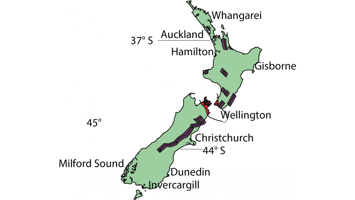
The location of the site relates to the wind region.
See Figure 1: New Zealand Region Map in the image gallery above
Building importance level and wind speed
A building’s importance relates to the building’s functions and post-disaster functionality, which used with the NCC works out the annual probability of exceedance of wind.
Terrain/Height Category (Mz,cat) AS/NZS 1170.2 Clause 4.2.1 & Table 4.1
- Terrain
- Height of Building;
- Direction of the wind (Md) AS/NZS 1170.2 Table 3.2.
- Shielding (Ms), AS/NZS 1170.2 Table 4.3
- Topographic (Mt), AS/NZS 1170.2 Clause 4.4
| Building Importance Level | Annual Probability of Exceedance per Year (Wind) |
|---|---|
| 1 | 1:100 Non-Cyclonic |
| 2 | 1:500 |
| 3 | 1:1000 |
| 4 | 1:2000 |
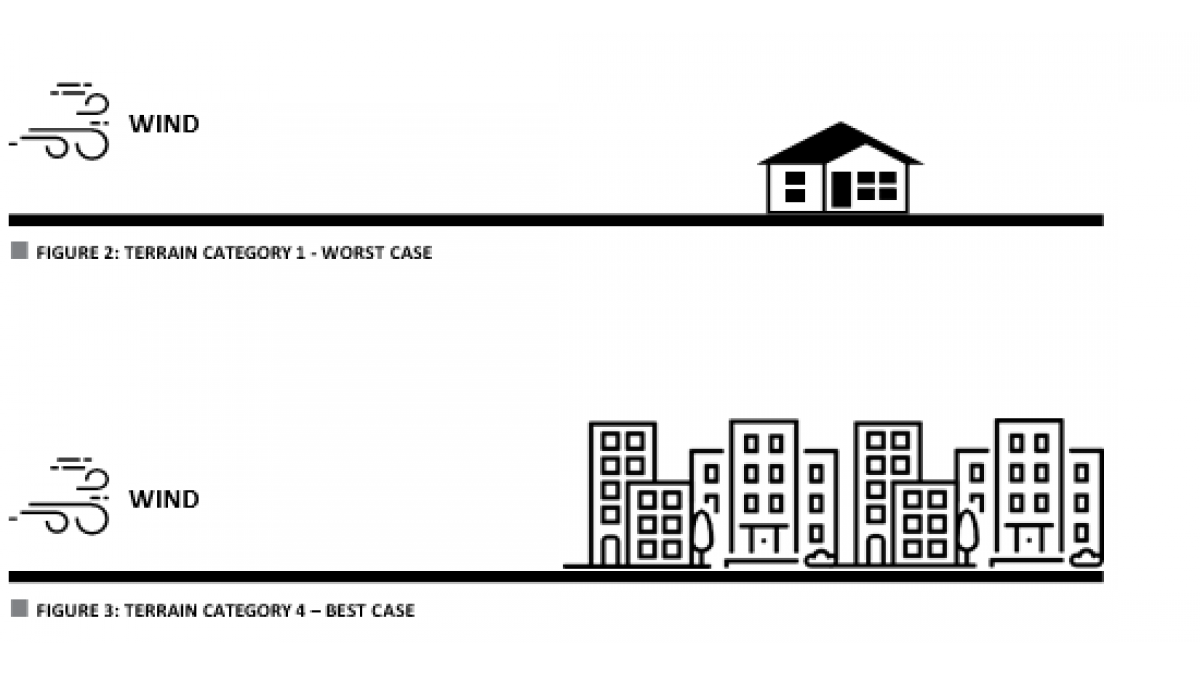
| Terrain Category | Description (General refer to AS/NZS 1170.2:2011 for full description |
|---|---|
| TC1 — Worst Case | Very exposed. Flat treeless plains with little grass eg. inland lakes or bays. |
| TC1.5 | Right on the shore of the ocean, sea. |
| TC2 | Farmland with well-scattered obstructions. |
| TC2.5 | New developments, urban areas with scattered buildings. Intermediate between TC2 and 3. |
| TC3 | Suburban areas, buildings close together with a general height of 3m – 10m. |
| TC4 — Best Case | City centres, buildings close together with a general height of 10m - 30m. |
See Figure 2 and 3: Terrain Category 1/4 — Best and Worst Case
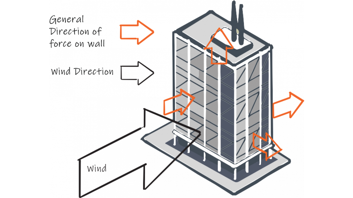
Aerodynamics of the structure
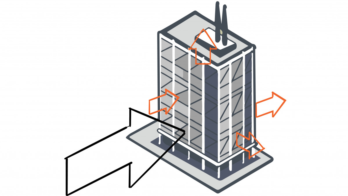
The shape/aerodynamics of a building influence the creation and location of positive and negative pressure zones. Negative pressure can be created when the wind blows past a surface. This pressure is
felt on the cladding which acts as a suction force. An engineer working on a building will need to factor in both the positive; wind pushing against the surfaces and negative.
See Figure 4: Wind Forces on a Building
Cladding: The first line of defence
A buildings first line of defence against the wind is its cladding. The cladding takes the full and fluctuating force of the wind, transferring it back to its sub structure and then onto the building structure.
Local pressure
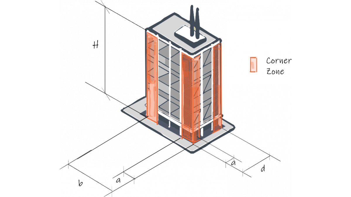
Zones of a building may have extra pressure applied due to the location or shape of the zone. A corner of a building will have increased factors applied because of extra wind pressure in these
areas.
To calculate the size of the corner zone (a) the other dimensions of the building need to be used.
When considering corner zones most building shapes will only require one corner zone which is equal to α/2 to be used, while some taller and slender buildings will require two corner zones = 0 > α/2 and α/2 > a.
a = The lowest of 0.2b, 0.2d or 1H
Where:
- a = Width of corner Zone
- b= Breadth of Building
- d =Depth of building
- H = Height of building


 New Products






 Popular Products from Rondo Building Services


 Most Popular


 Popular Blog Posts
