


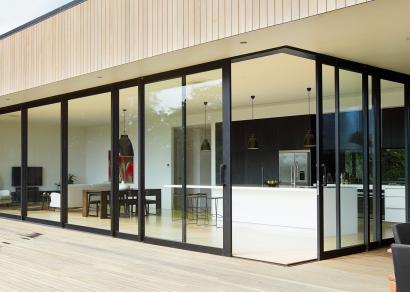
 VANTAGE Windows & Doors
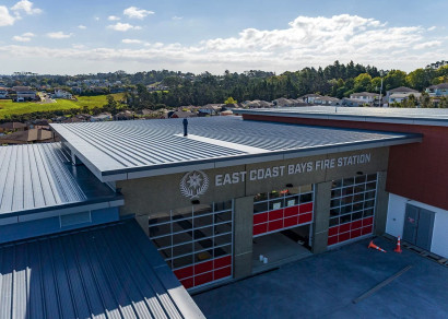
 Roofing Industries
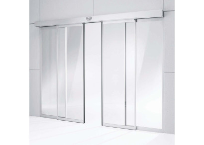
 dormakaba
 XLam Cross Laminated Timber Panels
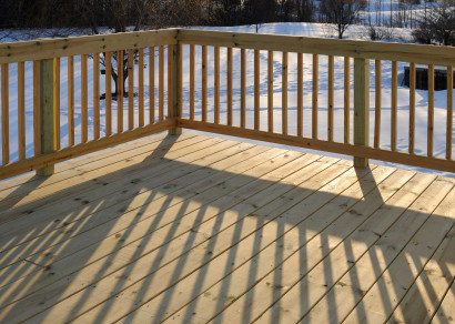
 SPAX
SPAX


 Bates Surfaces
 Case Studies
 JESANI
 Aero
Aero


")


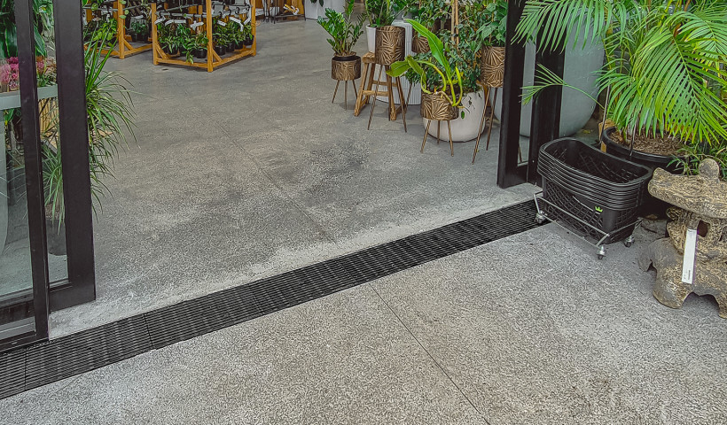
Insulated slabs have created a new design facet to achieving compliant level threshold systems to the acceptable solution outlined in Fig 17B and Chapter 7.3.2.1 of E2/AS1. Some additional attention should be given to the interaction between the insulated slab and the Perimeter Drain to achieve the best solution for both elements.
Insulation of the slab as required by H1 is achieved by the installation of a polystyrene or XPS sheet that is then covered, or supplied with, a cement-based render. This render can have the selected membrane system applied to it which will isolate the building envelope from the exterior drain and separate the two systems.
At this point it is very important to select a system that will interact with the insulated section and have allowances to meet the requirements of both E2 and H1. The selection of a system will influence the cost, compliance, install details and durability of the system once installed and commissioned.
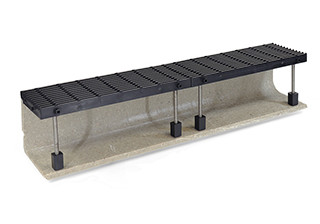
The building envelope that is created by the membraned edge cannot be penetrated by any fixings, as this will transfer moisture and will penetrate the thermal break provided by the insulated section. A perimeter drain with an open side can be located against the vertical membraned face and achieve the E2 detail without compromising the calculated insulation values for the slab. Once the perimeter channel is installed, the membraned vertical face can then be bandaged and lapped into the base of the screeded channel to finish the membrane detail. All of the components of the perimeter drain allow for grates that are removable and separate from the building line, allowing a clear 12mm gap between for water off the joinery to fall into the channel. (E2/AS1 Ch 7.3.2.1 (b))
Insulated slabs will sometimes create a sill detail that will protrude out past the joinery line, or step in from the foundation. A brick façade or rendered sill for example. Attention should be paid here to allow enough depth for the grating system to cantilever over the insulated sill and maintain clearances for water to travel unimpeded to the channel below. Having any part of the system in contact with the slab edge will not achieve this, for example a three-sided channel. So, the use of a custom bracket can allow both the insulation and grating detail to operate and be supported independently to meet acceptable solutions.
The use of Allproof’s Perimeter drain system allows the insulated building slab and exterior drainage solution to work in harmony ensuring compliance in the H1 and E2 solution. Allproof works with other industry suppliers to ensure that the details offered are acceptable to both solutions and will not compromise either's warranties once the detail is finalised. Talking with suppliers and engaging them during the design phase can help ensure that the detail on site is achievable and will result in a compliant, robust, and aesthetically pleasing result to the finished project.


 Popular Products from Allproof Industries

 Posts by Andrew Smith

 Most Popular

