A typical residential project will likely require various surface water drainage systems installed at the property entrances and at the property boundary to protect the building from moisture and mitigate runoff into the street. Each scenario will have different requirements based on its performance needs and applicable building codes. The following describes typical scenarios you may face and how these systems would converge before surface water can be drained into the local authorities stormwater system.
Garage and driveway drain
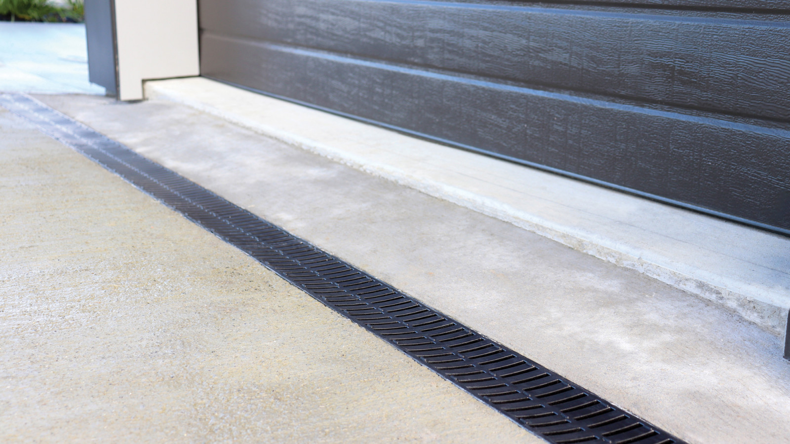
For attached garages (areas not deemed to be habited spaces), the door openings will have a “50mm minimum total level change between the interior and the exterior paving” (E2/AS2 clause 9.1.3.4) in the way of a nib and/or ramp. A drainage channel would then be installed across the total opening width. The same channel drainage system would likely be present at the driveway entrance along the property boundary to collect runoff from the property. Factors to consider would be channel depth, load rating and grate selection.
When selecting a grate for a low traffic area that will be subjected to vehicles it is advisable to consider the likelihood of grate dishing and ongoing material finish (i.e. oxidisation in cast iron). For areas which will be subject to domestic vehicles, a high grade plastic channel system that gains its strength from surrounding concrete, such as Allproof's Domestic Channel system, is recommended. If a higher load rating as per AS3996 is required in the situation where commercial vehicles or heavy loads such as boat trailers need to access the property, a heavier duty option such as Allproof’s Polymer Concrete would provide an excellent alternative. Grade 316 stainless steel Wedge Wire (load class B or above) would make an excellent grate option in this situation. The appearance and shape of the channel's grates should be able to last under repeated wheel loads.
Level threshold entry
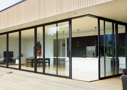
At the main entrance to the dwelling, a level threshold may be desired where the internal surface and external surface are not subjected to a level change. In this scenario E2/AS2 clause 7.3.2 applies. A 150mm deep by 200mm wide channel is required across the entrance with a grating system that will maintain a 12mm separation (drip line) from the joinery. A traditional three-sided channel doesn't work in this scenario as the joinery traditionally overhangs the building slab and will often vary in its width creating a narrower reveal in certain areas. Features to consider here would be the grate finish/material and slip resistance in accordance with AS4586.
A two-sided channel solution such as Allproof's off-the-shelf Perimeter Drain would be recommended here, with grate options chosen to meet finish and slip resistance requirements. In the case of Allproof's Perimeter Drain, a Glass Filled Nylon (GFN) grate option provides an R10 Slip rating and offers a matt black finish to complement joinery, while a fully custom stainless steel grate supported by a bracket is available to meet an R11 slip rating.
For more detailed information on designing the correct system and application for level threshold please see our article on How to Design E2 Compliant Level Access Building Entrances.
Sump/collection point
In a central or practical location a sump should be installed. This sump can be used to drain the surrounding surface area by creating falls towards it and therefore positioned accordingly, or it can be used as a collection point for the property’s other drainage systems. The sump's purpose is to provide suitable collection capacity for surface water from the surrounding area, provide sediment catchment while removing the likelihood of floatable solids entering the stormwater system and providing access for maintenance and cleaning. E1/AS1 states in clause 3.6.1 that “all surface water, except that collected directly from a roof, shall enter the drain via a sump which has:
- A) A grating, hinged or removable for maintenance access. The grating shall comprise at least 35% openings. The smaller dimension of any individual opening shall not exceed 35mm.
- B) Capacity at the bottom for settlement of silt and debris, and
- C) A submerged (or trapped) outlet which prevents floatable solids entering the drain”
The channel systems previously highlighted all have outlet locations on the underside of each channel section; the stormwater pipe would then drain the collected surface water away from the building and into the above sump. Allproof’s DP350x700RS has recently been brought to the market, the sump complies to the above E1/AS1 clause 3.6.1 with a round cast iron grate, 300mm of sediment collection and enough space above to include a half syphon outlet.
The full system
Other drainage systems such as storm grates may also be required depending on the design of the property, these will follow a similar process and integration with the full system. A level of continuity can be achieved by selecting complementary systems from the same supplier. Often grates and details are transferable between products allowing for an aesthetic language to be kept throughout the project.












 Most Popular
 Popular Products


